![]()
![]()
The Optics Laboratory
Group of
Hans Hallen, North Carolina State University Physics Department![]()
![]()
![]()
The Optics Laboratory
Group of
Hans Hallen, North Carolina State University Physics Department![]()
Distance Regulation
•
• Lateral Probe Resonance
• Driving the Oscillation
• Sensing the Tip Motion
- Historical Methods
- A Sampling of New Methods
- The Lock-in Amplifier is Not Necessary
The feedback system:
•
•
How do we maintain distance in NSOM?•
It should be independent of the detected light. -provides a 2nd image (topography)•
Consider the mechanical modes of the tapered fiber probe.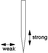
•
Vibrate tip laterally at resonance to measure the lateral force (through vibration amplitude).•
The probe is stiff in the perpendicular to the sample so it is not susceptible to being pulled to the sample by attractive, capillary, forces.•
Method:- Establish oscillation at resonance. - Set feedback request for a smaller level. - Approach until feedback system takes over.
- The glue joints should not have excess glue (or reduced Q), and should dry completely (or resonance frequency drifts). They are typically the weakest mechanical link.
•
Mechanism:- At small amplitudes it is probably due to adsorbed layer interactions or boundary layer friction.
- At large amplitudes it is tapping -- a nonlinear bending force: M.J. Gregor, P.G. Blome, J. Schöfer, and R.G. Ulbrich, APL 68 (3) 307-9 (1996).
- C. Durkin, I.V. Shvets JAP 80 (10) 5659-64 (1996).
Probe Resonance Frequency
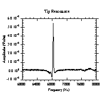
A resonance peak from a fiber optic probe tip is shown where the resonance frequency is 68.4 kHz and the Q is 380. The resonance is driven by the center of mass oscillator described below, and the tip oscillation detected by an optical lever arm method.
In water, the Q-factor will decrease, but feedback is possible.
E. Betzig in Near Field Optics, D.W. Pohl and D. Courjon, eds. (Arc-et-Senans, France, Kluwer) 1993, 7.
H. Muramatsu et al, Thin Solid Films 273 (1-2) 335-8 (1996) and APL 66 (24) 132 (1995)
P.J. Moyer and S.B. Kammer, APL 68 (24) 3380-2 (1996).
T. Okajima, S. Hirotsu, APL 71 (4) 545-7 (1997).
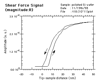
Approach curve:Tip vibration amplitude.
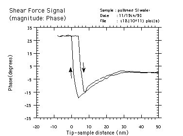
Approach curve:Phase.
Driving the Oscillation
•
•
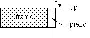
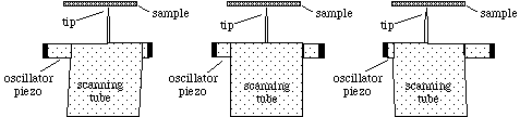
The piezo is mounted to the frame and the sample to the scanner.•
But for large samples the tip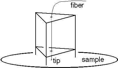 should be scanned.
- Problem: The scanning tube 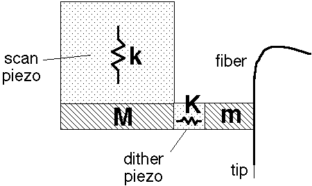 is flexible at 50 kHz, so M moves making m's motion less than that of the dither piezo
- Take advantage of this free-floating-at-high- frequency problem with the 'center of mass oscillator.'
The 'Center of Mass' Oscillator
C.L. Jahncke and H.D. Hallen, "A versatile, stable scanning proximal probe microscope," Rev. of Sci. Instr, 68 (4), 1759 (1997).
-Lateral oscillation of the probe is shown schematically at a few points of the motion. As the oscillator piezos change their mass distribution, the probe and other mass at the end of the scan tube must move to compensate since the tube can be modeled as a weak spring which freely bends at the driven frequency.
•
The design also permits reflection collection optics which are - high numeric aperture, and- do not have shadowing problems:
- since the driving piezo is out of the way.
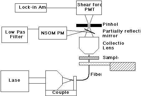
One of the oldest motion detectors -- the pinhole method:
E. Betzig, P.L. Finn and J.S. Weiner, APL 60 (20) 2484-6 (1992).
• This uses light which is scattered by (or sent through) the tip for feedback.
• The tip appears as a point source of light from the perspective of the detector, so a pinhole in the image plane selects this light.
• As the tip oscillates, so does the point in the image plane, so the light through the pinhole is modulated -- in relation to the tip amplitude.
• The same light used for the NSOM measurement can also be used for shear force detection, by splitting the freq. components (i.e. low pass filter the NSOM signal).
•
A drawback is that the magnitude of the force feedback signal can depend on the sample transmittance, so it works best for uniform samples.
Another Oldest -- an interferometric method
•
Developed simultaneously but independently:P.C. Yang, Y. Chen, M. Vaez-Iravani, JAP 71, 2499 (1992), and R. Toledo-Crow, P.C. Yang, Y. Chen, M. Vaez-Iravani, APL 60 (24) 2957-9 (1992).
• Laser intensity fluctuations can be a problem - one can compensate by using a split diode or measuring a fraction of the laser light.
• But using the phase of the light is more robust.
• Build an interferometer where the arms carry light of different polarization.
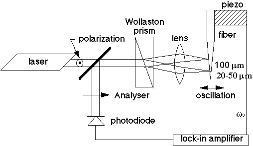
•
Wollaston axes are 45° w.r.t. the input pol.• The apparent plane of splitting of light is at the focus of the lens so both beams are focused on the shaft ~100
µm apart.
The classic optical lever arm method
for example P.J. Moyer and M.A. Paesler, SPIE 1855, 58-66 (1993).
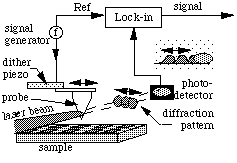
A laser beam focused on the sample creates a diffraction pattern whose motion reflects that of the tip. The diffraction pattern motion is measured by a detector with its edge on the side of a diffraction peak.
•
Laser -- HeNe or diode lasers. - infrared diode lasers have been used when the red light would have unwanted effects (e.g. excitation of carriers in a semiconductor)• the light that passes very close to the narrow probe produces a diffraction pattern.
•
The diffraction pattern: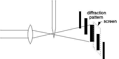
•
the edge of the screen is positioned where there is a large gradient of intensity (side of a line) to maximize signal change as the pattern shifts due to the tip motion.• An asperity on the side of the tip can also scatter light which will reflect the level of tip vibrations and can be seen at other angles.
• The detected signal (by a photodiode) is fed into a lock-in amplifier operating at the same frequency as the tip oscillates.
• The oscillation frequency is set by ramping the frequency while monitoring the detector output.
• Both tip resonances and those from the piezo which drives the tip will be seen.
• Typical fiber Q's are few 100 (air), 20 in water.
• Frequencies can be estimated from a bending beam formula (a few 10's of kHz for 2-3 mm fiber extending from the holder).
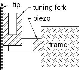
The Tuning Fork
K. Karrai and R.D. Grober, APL 66, 1842 (1995).
K. Karrai and R.D. Grober, Ultramicroscopy 61 (1-4) 197-205 (1995).
A.G.T. Ruiter et al, APL 71 (1) 28-30 (1997).
• Probably the most commonly used method now
• The tuning fork is really a watch crystal with the can removed.
• Usually drive with another piezo at the fork resonance and detect the voltage on the fork.
• The fiber extends only slightly from the fork so its resonance is far above the driving freq.
• Attaching the fiber (usually super glue) is hard and critical.
•
Many other arrangements are possible - Drive at fiber resonance.- Drive/ detect with fork (special case of impedance method below).
- Time division drive/ detect (Yung Hui Chuang et al, APL 69 (22) 3312-14 (1996)).
The impedance method
•
J.W.P. Hsu, M. Lee and B.S. Deaver, "A Non-optical Tip-sample Distance Control Method for Near-field Scanning Optical Microscopy Using Impedance Changes in an Electromechanical System," RSI 66 (5) 3177-81 (1996).• M. Lee, E.B. McDaniel, J.W.P. Hsu, "An Impedance Based Non-Contact Feedback Control System for Scanning Probe Microscopes," RSI 67(4) 1468-71 (1996).
• Forces on the piezo originating from the shear
force change its shape and hence capacitance.
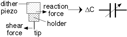
•
The dither piezo must be rigidly held so that the forces can distort it.• The holder and joints must be rigid at drive freq.
•
The signal at the tip resonance is nulled with an active bridge circuit and monitored with a lock-in amplifier.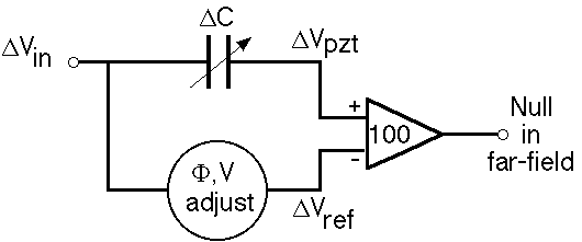
•
Feedback is set at some nonzero bridge offset.
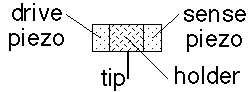
The matched oscillator/detector method
R. Brunner, A. Bietsch, O. Hollricher, and O. Marti, RSI 68 (4) 1769-72 (1997).
• The drive is very similar to the geometry of the center of mass oscillator (which we run this way now), but one side drives while the other senses.
•
Again, the tip holder and joints must be rigid.•
The voltage across the sense piezo is monitored•
For reduced pick-up, the two piezo's should not share the same ground.• As in all sensitive detection schemes, any metal between the scanner piezo and sensing piezo should be grounded as a shield.
Normal (not shear) force detection methods:
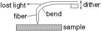
Bent fiber methods:
Klony Lieberman,Nily Ben-Ami, Aaron Lewis, RSI 67 (10) 3567 (1996).
R.T. Stevenson et al, RSI 67 (11) 3891-7 (1996).
Din Ping Tsai, Wen Rei Guo, J. Vac Sci. Technol. A15 (3) pt2
1442-5 (1997).
• A standard fiber tip is held sideways and heated (CO2 laser) until it bends.
• The mounting is reminiscent of the old wire AFM probes.
•
The light lost at the bend must be shielded, and the input power increased to compensate.
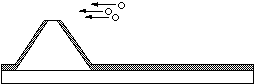
Probes based on commercial AFM cantilever/ tips:
M. Radmacher, P.E. Hillner and P.K. Hansma, RSI 65 (8) 2737-8 (1994) and many others since.
• The cantilevers are micro-machined to form an aperture, often with a focused ion beam after metal deposition on the front surface.
AFM ProbeMetal EvaporationFocused Ion Beam
![]()
![]()
•
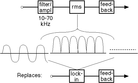
Detection without a lock-in amplifier
J. W. P. Hsu, A. A. McDaniel and H. D. Hallen, "A Shear Force Feedback Control System for Near-field Scanning Optical Microscopes without Lock-in Detection," RSI 68 (8), 3093-3095 (1997).
• Most modern tip motion detection schemes do not need or want phase information.
• The only signal present is the one of interest.
• Then the expensive (k$) lock-in is unnecessary and an RMS chip (~$10) works well.
• This is applicable to all forms of scanning probe microscopes with good clean signals.
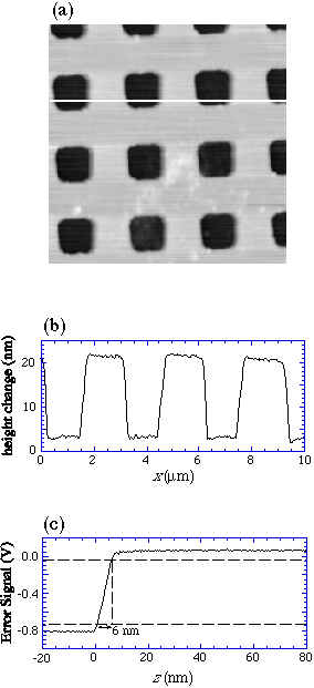
Force feedback images: impedance method without lock-in.
![]()
North Carolina State University | Physics | Optics Home
Last updated on September 27, 2000